Quality Management
FORESEEN OPTICS is committed to providing the highest quality optical rifle scopes, ensuring that our products lead the industry in optical performance, structural strength, and reticle accuracy. Below is an overview of our core internal quality management process, covering every stage from optical quality control to assembly error management.
| 1. Ensuring Optical Quality
Lens Precision Inspection
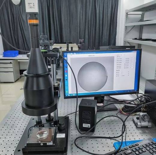
Lens precision is crucial to optical quality. Therefore, we conduct strict precision inspections during each stage of lens processing and assembly. We use high-precision interferometers to measure the lens surface shape, thickness, and curvature radius, ensuring lenses meet design specifications. Additionally, we use precise measuring equipment to inspect lens centration, ensuring the optical axis aligns with the mechanical center to prevent image distortion. Each batch of lenses undergoes rigorous random sampling to ensure product consistency. Every inspection record is meticulously documented and archived in our quality management system for traceability and analysis.
Lens Coating Inspection
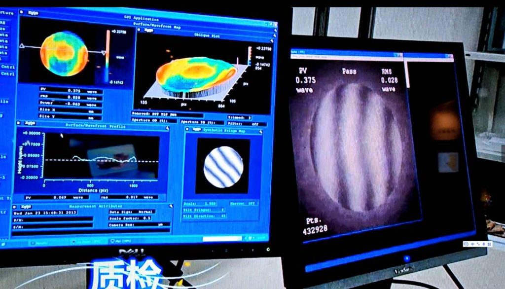
Coating is essential for enhancing lens optical performance. We strictly inspect each coating layer for thickness and uniformity. Specialized equipment is used to measure reflectance, transmittance, and coating thickness, ensuring each lens meets the highest optical performance standards. Coating inspections are conducted in cleanrooms to prevent dust or impurities from affecting coating quality. After coating, every lens undergoes strict spectral analysis to ensure coating uniformity and performance.
Finished Product Collimator Testing
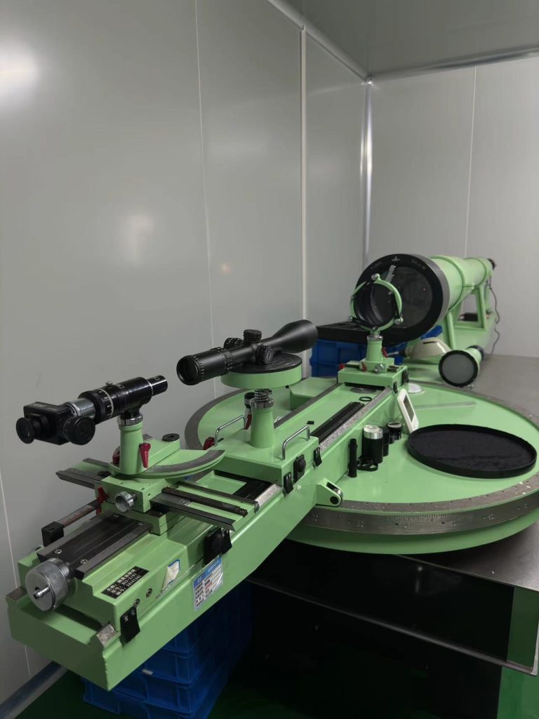
In the finished product inspection phase, we use collimators to test the optical system accuracy of rifle scopes. Collimator testing simulates the scope’s imaging performance in real-use scenarios, ensuring that the optical system is well-aligned and meets optical quality requirements. We conduct multiple imaging tests on each finished product to evaluate clarity, edge distortion, and field uniformity, ensuring compliance with optical design standards.
Inspector Visual Target Testing
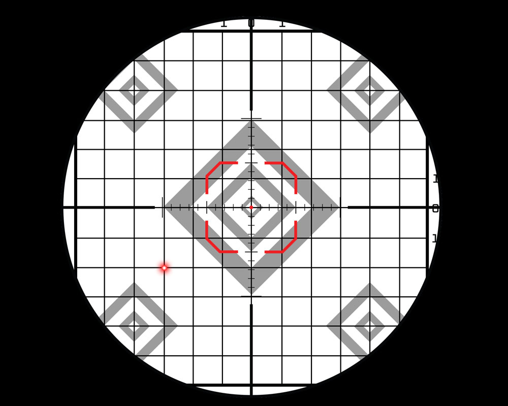
Our inspectors are highly trained professionals who conduct final inspections of optical performance through visual target testing. Inspectors use different magnifications to thoroughly evaluate image quality, clarity, contrast, and distortion, ensuring every rifle scope meets high optical standards. Each inspector undergoes rigorous training to identify even the slightest optical defects, guaranteeing high product quality.
| 2. Ensuring Structural Strength
Material Inspection for Component Manufacturing
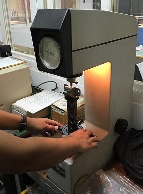
FORESEEN OPTICS conducts stringent quality inspections on each component to ensure it meets the strength requirements for rifle scopes. We test key materials, such as aluminum alloys, for hardness, tensile strength, ductility, and corrosion resistance to ensure stability in various environments. For critical components like housings and mounts, we conduct fatigue testing to simulate long-term stress conditions, ensuring material reliability.
Component Pre-Inspection
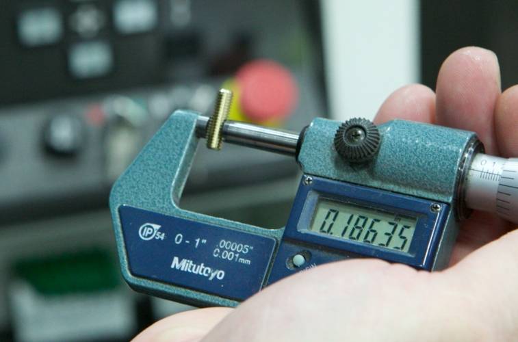
Before processing, we perform pre-inspections on all critical components to verify compliance with design specifications. We use quick fixtures and gauges for dimension fitting measurements, ensuring component precision aligns with standards. Pre-inspections effectively reduce the risk of dimensional deviations during machining, ensuring a smooth assembly process.
In-Process Sampling and Patrol Inspection
During machining, we have a rigorous sampling and patrol inspection process. Technicians perform sample inspections at critical stages, verifying component dimensions, surface quality, and geometry to ensure compliance. Patrol inspectors monitor the production site in real-time, addressing any issues immediately to maintain quality. Additionally, we monitor environmental factors like temperature and vibration during machining to ensure stable precision.
Impact Testing for Finished Products
To ensure the structural strength of rifle scopes, we conduct impact testing during the final product phase. Simulating extreme shocks, these tests evaluate the scope’s shock resistance. Multiple repeated impact tests ensure rifle scopes function under harsh conditions. All test data is documented and used for product improvement to meet customer expectations for robustness and durability.
| 3. Ensuring Reticle Accuracy
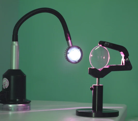
Reticle materials directly affect aiming accuracy. We conduct thorough inspections to ensure high optical transmittance and durability, meeting precision requirements. All materials undergo mechanical performance testing before storage to ensure consistent quality.
Reticle Transmittance Testing
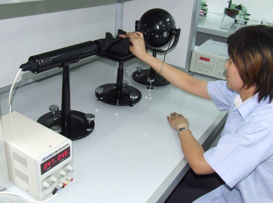
Transmittance is a key indicator of reticle quality. We use photometers to test transmittance, ensuring that it meets design standards without compromising the overall optical performance. Transmittance testing is conducted under strictly controlled lighting conditions to ensure accuracy.
Reticle Etching Inspection with Microscopy

The etched lines on the reticle are crucial to aiming accuracy. We use high-power microscopes to inspect etching depth, width, and positional accuracy, ensuring every line meets specifications without deviation or defect. Microscopic inspection identifies even the smallest etching defects, ensuring each reticle meets high precision standards.
Reticle Corrosion Resistance Testing
Reticles may be exposed to various environments during use, making corrosion resistance critical. We conduct corrosion resistance tests to ensure reticles remain accurate under long-term exposure to environmental factors. Each batch must pass these tests to ensure stability under harsh conditions.
Cleanroom Assembly

Reticle assembly is conducted in a cleanroom to prevent impurities from contaminating etched lines and compromising optical precision. We strictly monitor cleanroom conditions, including air quality, temperature, and humidity, to ensure optimal assembly conditions.
Final High and Low Magnification Visual Inspection
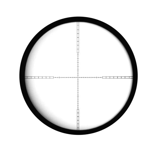
After assembly, each rifle scope undergoes 100% visual inspection at high and low magnifications. Inspectors evaluate image quality, reticle line clarity, and alignment to ensure precision. We also assess imaging performance under different lighting conditions to guarantee aiming accuracy across various environments.
| 4. Assembly Error Control
Use of Work Instructions
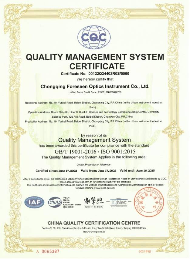
Under the ISO9001 quality management system, FORESEEN OPTICS strictly utilizes work instructions to standardize each assembly step. Employees follow these instructions to ensure consistent quality, reduce human error, and meet specifications for each stage of assembly.
Stability of Key Positions
We maintain stability in key assembly positions, such as lens assembly, scope tuning, reticle installation, sealing, and final checks, by ensuring that these roles are handled by professionally trained and experienced personnel. Regular training sessions are held to keep employees’ skills up to date with the latest requirements, effectively minimizing errors.
On-Site Patrol Inspection System
To further minimize errors during assembly, FORESEEN OPTICS implements a strict on-site patrol inspection system. Quality inspectors perform real-time checks at the assembly site, promptly identifying and correcting any issues. Detailed records are kept for each patrol inspection for later analysis and continuous improvement.
100% Inspection of Key Positions
For key positions such as lens assembly, scope adjustment, reticle installation, sealing, and packaging, we implement a 100% inspection policy. Each product must pass comprehensive quality checks before leaving these key steps. Inspections cover optical performance, mechanical strength, and sealing to ensure high-quality output.
Quality Feedback and Improvement
If any quality issues are detected during assembly, they are immediately reported to the relevant departments for root cause analysis and corrective action. Each corrective measure is documented and tracked to prevent recurrence. Through continuous feedback and improvement, we ensure that every rifle scope meets the highest standards set by our customers.
With these comprehensive quality management processes, FORESEEN OPTICS ensures superior performance in optical quality, structural strength, and reticle precision for our rifle scopes. We maintain stringent quality standards, constantly improving and optimizing our processes to meet customers’ needs for high-quality optical products.
We also support third-party inspections and customer on-site audits and are willing to collaborate with experienced quality control personnel to produce rifle scopes that meet customer expectations.
| 5. FORESEEN OPTICS Rifle Scope Manufacturing Standards
1. Scope
This standard is jointly drafted by the Customer Service Department and the Production Department of FORESEEN OPTICS. It clearly defines the technical requirements, testing methods, inspection rules, as well as the specifications for marking, packaging, transportation, and storage of rifle scopes (hereinafter referred to as “scopes”). The goal of this standard is to promote high-quality industry development, taking into account the diverse characteristics of different brands, focusing on meeting the practical needs and user experience of custom clients. It is committed to providing reliable, high-performance, and competitively sustainable rifle scopes for the brands served by FORESEEN OPTICS.
2. Normative References
The following documents are essential for the application of this document. For referenced documents with a specified date, only the version dated is applicable to this document; for those without a date, the latest version (including all amendments) applies to this document.
- ISO 780:2015 Packaging. Distribution packaging. Graphical symbols for handling and storage of packages
- GB/T 1185-2006 Surface imperfections of optical elements
- FORESEEN OPTICS Customer Special Requirements Collection Form
3. Requirements
3.1 Optical Performance
The allowable errors and values for the optical performance indicators of the scope are shown in the table below. If there are special requirements in the customer communication form, adjustments must be made according to the values specified in the customer communication form:
| Parameter Name | Allowable Error and Indicator Values |
| Eye Relief | ≥3″ |
| Magnification | ±5%(high magnification)、±10%(low magnification) |
| Exit Pupil Diameter | D/magnification,±15%(high magnification)、±25%(low magnification≥2)、±40%(low magnification<2) |
| Field of View | ±5% |
| Central Resolution | ≤300/D |
| Parallax | <0.25 diopter |
Note: Drepresents the effective diameter of the objective lens.
3.2 Structural Performance
The allowable errors and values for the structural performance indicators of the scope are shown in the table below. If there are special requirements in the customer communication form, adjustments must be made according to the values specified in the customer communication form:
| Parameter Name | Allowable Error and Indicator Values |
| Eyepiece Focusing Range | ≥+1.5to ≤-1.5diopters |
| Reticle Tilt | ≤1.5MOA(within the adjustment range) |
| Adjustment Range | ≥200MOA(for products with ≥10x magnification),≥250MOA(for products with <10x magnification) |
| Click Value Deviation | ±10%(0.25MOA/CLICK products),±15%(0.125MOA/CLICK products) |
| W/E Shift | ≤1MOA(in all directions) |
| Zoom Shift | ≤1.5MOA |
| Misalignment | ≤1.5MOA |
Note: If the values do not conform to Table 1 or Table 2, the technical specifications provided by the customer shall apply.
Moving Parts
All moving parts of the scope should operate smoothly, without looseness or jamming. Rotating parts should be able to stop freely at any position within their travel range.
Damping Force
Under the premise of meeting the requirements in Section 3.2.2, if there are special requirements in the customer communication form, adjustments should be made according to the values specified in the customer communication form. The damping force standard should be measured at 25°C (Celsius). The best approach is to send production samples for testing and sealing.
3.3 Environmental Adaptability
Vibration Resistance
After the test in Section 3.13, there should be no looseness or damage, and the center offset should be less than 1.5 MOA. The requirements of Section 3.4.5 must be met.
Waterproof Performance
After the test in Section 3.14, there should be no leakage.
Fogproof Performance
After the test in Section 3.4.15, there should be no fogging inside the scope, or any fog should be cleared within 7 minutes.
3.4 Appearance and Cleanliness
- The surface color of the same type of processing on the same scope should be consistent.
- The surface of the components should be free from burrs and sharp edges
- The surface decoration of the scope should meet relevant standards, and the coating, oxidation layer, and plating on the outer surface should be stable.
- There should be no excess grease on the outer surface of the scope; adhesive areas should be free from residual adhesive layers; finely finished areas should not have noticeable scratches or damage.
- When viewed from the eyepiece side, there should be no visible dust, burrs, or other contaminants within the field of view; when viewed from the objective lens side, the inner wall of the scope tube should not have visible grease buildup, large metal shavings, or other debris.
- The above requirements are based on visual inspection. Due to significant differences between individuals, the standards should be confirmed with the customer before mass production. The reference for resolving discrepancies should be the third-party standard for general goods inspection.
3.5 Optical Component Surface Quality
- Optical components of the scope should not have obvious coating or adhesive peeling.
- The bevel edges of optical components, including any partial chip damage and size, should comply with the provisions of GB/T1185. When viewed from the eyepiece or objective lens direction, no reflections caused by chipped edges should be visible.
- When viewed from the eyepiece and objective lens direction, optical components should not have visible pit marks, chips, bubbles, or scratches.
4. Testing Methods
4.1 Eye Relief
Measured using an optical bench.
4.2 Magnification
Measured with a dynameter.
4.3 Exit Pupil Diameter
Measured using an optical bench or dynameter.
4.4 Field of View
Measured using a field-of-view tester.
4.5 Center Resolution
Measured using a resolution test target on an optical bench.
4.6 Parallax
Measured with a diopter tester on a collimator.
4.7 Eyepiece Focusing Range (Diopter Range)
Move the eyepiece or eyepiece housing forward (for fast-focus products) to the limit and measure the maximum negative diopter with the diopter tester; then move the eyepiece tube or eyepiece housing backward (for fast-focus products) to the limit and measure the maximum positive diopter with the diopter tester.
4.8 Reticle Tilt
Adjust the scope on the alignment tool so that the reticle crosshair of the scope aligns with the crosshair of the instrument. Then, adjust the “UP” turret of the scope, and observe the changes in the scale of vertical and horizontal shifts at the center of the reticle. The tilt angle of the reticle can be calculated using trigonometric functions.
4.9 Adjustment Range
Adjust the scope on the alignment tool so that the reticle crosshair of the scope aligns with the horizontal crosshair of the instrument. Then, adjust the “UP” and “R” turrets to set the extreme positions of the reticle’s center, both vertically and horizontally. The scale of these extreme positions will define the adjustment range: “UP” (up), “DOWN” (down), “L” (left), and “R” (right) adjustment range.
4.10 Click Value
Adjust the scope on the alignment tool so that the reticle crosshair of the scope aligns with the horizontal crosshair of the instrument. Then, adjust the “R” turret and record the number of clicks of the “R” turret while the reticle moves vertically from the L position (200 MOA) to the R position (200 MOA). The number of clicks, denoted as “S,” can be used to calculate the CLICK value: (20 × 200) / S.
4.11 W/E Shift
Check the status of the turrets using the alignment tool. Under normal conditions, the movement should be completely stable. If there is an issue, a jumping shift will occur, which can be directly observed on the calibration instrument. The shift refers to the offset caused by scale misalignment.
4.12 Zoom Adjustment Stability
After rotating the zoom knob and achieving a clear focus, measure the displacement value of the point’s position relative to the center of the field of view. The alignment tool can directly read this value.
4.13 Vibration Test
The scope, after being centered and adjusted for parallax, is mounted on a shock platform fixture. It undergoes 5500 shocks with an impact force of 1200g. Its internal performance and external appearance are then examined. The impact force and number of shocks can be adjusted based on customer requirements for the scope.
4.14 Waterproof Test
Submerge the scope in water at a depth of 254mm (10″) and a temperature of 52°C for 3 minutes. After removal, check for any water ingress inside. This test can be adjusted based on the customer’s requirements for the scope.
4.15 Fogproof Test
Place the scope in a freezer at -15°C ± 2°C for 30 minutes. Then remove it and check at room temperature (20°C ± 2°C) for any fogging. This test can be adjusted based on the customer’s requirements for the scope.
4.16 Moving Parts
Test by tactile feedback. Follow the customer’s suggestions for the sample and conduct sample sealing for standardization.
4.17 Appearance and Cleanliness
Visual inspection, tactile inspection, and comparison with samples.
4.18 Optical Component Surface Quality
Visual inspection.
5. Inspection Rules
5.1 Products must pass the company’s quality inspection department’s technical standard tests before leaving the factory, and a certificate of conformity (optional for the customer) must be attached.
5.2 Classification of Inspections
The inspection of scopes is divided into factory inspections and type inspections.
Factory Inspection
For small production batches, full inspection may be conducted. For larger production batches, inspections shall be conducted in accordance with the provisions of Tables 3 and 4, and nonconformance shall be determined accordingly.
Table 3 Inspection Methods
| Parameter Name | Requirement | Test Method | Sampling Category |
| Eye Relief | 3.1 | 4.1 | IX |
| Magnification | 3.1 | 4.2 | IX |
| Exit Pupil Diameter | 3.1 | 4.3 | IX |
| Field of View | 3.1 | 4.4 | IX |
| Center Resolution | 3.1 | 4.5 | I、VI |
| Parallax | 3.1 | 4.6 | II、VII |
| Eyepiece Focusing Range | 3.2.1 | 4.7 | VI |
| Reticle Tilt | 3.2.1 | 4.8 | II、VI |
| Adjustment Range | 3.2.1 | 4.9 | II、VI |
| Click Value | 3.2.1 | 4.10 | VI |
| W/E Shift | 3.2.1 | 4.11 | I、VI |
| Zoom Shift | 3.2.1 | 4.12 | I、VI |
| Vibration Test | 3.3.1 | 4.13 | VIII、IX |
| Waterproof Test | 3.3.2 | 4.14 | VIII、IX |
| Fogproof Test | 3.3.3 | 4.15 | VIII、IX |
| Moving Parts | 3.2.2 | 4.16 | II、VIII |
| Appearance and Cleanliness | 3.4 | 4.17 | II、VI |
| Optical Component Surface Quality | 3.5 | 4.18 | II、VI |
Table 4: Sampling Quantity and Nonconformity Determination:
| Sampling Category | Quantity Range | Sample Size | Acceptance Number | Rejection Number |
| I | ≤280 | 20 | 2 | 3 |
| 281~500 | 30 | 4 | 5 | |
| 501~1200 | 40 | 6 | 7 | |
| 1201~3200 | 50 | 8 | 9 | |
| ≥3201 | 60 | 10 | 11 | |
| II | ≤280 | 20 | 1 | 2 |
| 281~500 | 30 | 2 | 3 | |
| 501~1200 | 40 | 3 | 4 | |
| 1201~3200 | 50 | 4 | 5 | |
| ≥3201 | 60 | 5 | 6 | |
| III | ≤280 | 13 | 2 | 3 |
| 281~500 | 20 | 3 | 4 | |
| 501~1200 | 32 | 5 | 6 | |
| ≥1201 | 40 | 6 | 7 | |
| IV | ≤280 | 5 | 2 | 3 |
| 281~500 | 8 | 3 | 4 | |
| 501~1200 | 13 | 4 | 5 | |
| ≥1201 | 20 | 5 | 6 | |
| V | ≤280 | 5 | 1 | 2 |
| 281~500 | 20 | 2 | 3 | |
| 501~1200 | 32 | 3 | 4 | |
| ≥1201 | 40 | 4 | 5 | |
| VI | ≤280 | 5 | 0 | 1 |
| 281~500 | 8 | 2 | 3 | |
| 501~1200 | 13 | 3 | 4 | |
| ≥1201 | 20 | 4 | 5 | |
| VII | ≤280 | 5 | 0 | 1 |
| 281~500 | 8 | 1 | 2 | |
| 501~1200 | 13 | 1 | 2 | |
| ≥1201 | 20 | 2 | 3 | |
| VIII | ≤280 | 5 | 0 | 1 |
| 281~500 | 8 | 0 | 1 | |
| 501~1200 | 13 | 1 | 2 | |
| ≥1201 | 20 | 1 | 2 | |
| IX | ≤280 | 1 | 0 | 1 |
| 281~500 | 2 | 0 | 1 | |
| 501~1200 | 3 | 0 | 1 | |
| ≥1201 | 3 | 0 | 1 |
Type Inspection
The type inspection items include all the items listed in Chapter 3 of this standard. Type inspection should be conducted under any of the following circumstances:
- a) When a new product is being developed and requires prototype identification;
- b) When significant changes in structure, process, or materials occur that may affect product quality;
- c) When production resumes after being halted for more than six months;
- d) During normal production, at least once a year;
- e) When required by national quality supervision and inspection agencies;
- f) When a customer pays to request a reinspection.
5.3 Batch, Sampling, and Conformance Determination
Sampling, inspection, and determination shall be carried out in accordance with Tables 3 and 4.
5.4 Determination Rules
If any nonconforming items are found in the inspection results, double the sample size may be selected from the batch for reinspection of the nonconforming items. If the reinspection still shows nonconformity, the entire batch of products shall be deemed nonconforming.
6. Marking, Packaging, Transportation, and Storage
6.1 Marking
Product Marking
The markings shall include the following: manufacturer’s name, address, product name, model, specifications, and product standard number. If the customer has specific requirements, the markings shall comply with their requests.
Packaging Marking
The packaging markings shall include: product standard number, product name, model and specifications, quantity, manufacturer’s name, and address. If the customer has specific requirements, the markings shall comply with their requests.
Graphic Symbols of Markings
The graphic symbols of markings shall comply with the provisions of ISO 780:2015.
6.2 Packaging
The product shall be wrapped in a plastic bag, followed by intermediate packaging in a cardboard box, and finally packed in a corrugated carton for bulk packaging. If the customer has special requirements, packaging shall be carried out according to the terms of the contract.
6.3 Transportation
Protection Requirements
- The product should be protected from direct exposure to sunlight, rain, and high-humidity environments. For pallet transportation, waterproof and dustproof protective layers must be applied outside the cartons to ensure the integrity of the external packaging under all weather conditions.
- Packaging materials shall have good compression resistance, shock resistance, and moisture-proof performance to prevent damage to the product due to external forces or environmental changes during transportation.
Loading and Handling
- Products must be loaded strictly according to the designated stacking method to ensure stable stacking and prevent tipping, sliding, or crushing.
- During loading and unloading, products must be handled with care, and throwing, rolling, or dragging is strictly prohibited to avoid mechanical damage.
- Appropriate forklift tools should be used for palletized packaging.
Transportation Equipment Requirements
- Transportation equipment should be kept clean and dry, free of corrosive substances. The cargo compartment should be equipped with anti-slip and shock-absorbing devices to prevent adverse effects on the product caused by bumps and impacts.
- For long-distance transportation, transportation plans should be reasonably arranged based on road conditions and climate to avoid transportation during adverse weather and poor road conditions.
Temperature and Humidity Control
- During transportation, the environmental temperature should be maintained between -20°C and +50°C, and the relative humidity should not exceed 80%.
- Under special climatic conditions, insulation or dehumidification measures should be taken to ensure that the product’s performance is not affected by temperature and humidity changes.
Labels and Instructions
- Clear instructions for transportation and storage, including symbols such as “Moisture-proof,” “Shockproof,” “Do not invert,” and “Handle with care,” shall be marked on the packaging.
- A unique identification code should be affixed to the outer packaging of the product to facilitate tracking and management during transportation.
Emergency Measures
- An emergency handling plan for transportation processes shall be established, including procedures for dealing with damaged packaging, product damage, or transportation delays to ensure that unexpected situations are promptly and properly addressed.
6.4 Storage
Storage Environment Requirements
- The scope should be stored in a dry, well-ventilated warehouse to avoid damage caused by high humidity or extreme temperature environments. The relative humidity in the warehouse should be controlled between 40% and 70%, and the temperature should be maintained between -10°C and 40°C to ensure the long-term stability of product performance.
- The storage environment should avoid direct sunlight and be kept away from heat sources or cold sources to prevent stress changes in optical components or performance degradation caused by temperature fluctuations.
Anti-Corrosion Measures
- The warehouse should be free of corrosive chemicals such as acids and alkalis and harmful gases to prevent corrosion of metal parts and damage to optical coatings on the product.
- If the storage conditions may become humid, an adequate number of desiccants or dehumidifiers should be installed in the warehouse to maintain the air humidity within a safe range.
Stacking and Protection
- Products should be neatly stacked by batch, and the stacking height must not exceed the pressure limits of the packaging. Stability must be ensured to prevent tipping and damage.
- The original dustproof, shockproof, and waterproof materials of the packaging should be retained to protect product quality from long-term storage or unexpected environmental changes.
Regular Inspection
- During storage, the products should be periodically inspected for quality, including the integrity of the outer packaging, clarity of markings, moisture conditions, and whether internal components show any abnormalities.
- Any abnormalities found should be promptly addressed, and corrective actions such as replacing the packaging or moisture-proof treatment should be taken as needed.
Long-Term Storage Considerations
- For products stored for more than six months, packaging and appearance inspection must be performed before leaving the factory. For products stored for more than one year, functional tests must also be conducted to ensure that the optical system, mechanical adjustment mechanisms, and sealing performance are unaffected.
- During storage, if handling or repackaging is necessary, the loading and handling specifications must be strictly followed to avoid accidental damage.

